An atmospheric water generator, or AWG, collects water from the surrounding air. Some designs chill humid air so that its water vapor turns into liquid. Others use materials that take up vapor and release it in a separate step [1]. The choice of method starts with the conditions where the device would operate. It also depends on the need the device would serve. Where usable fresh water is scarce, local water supply and the infrastructure to move and deliver it are separate parts of the problem [4].
Humidity and the dew point
Humidity describes the water vapor mixed with the air. Absolute humidity is the mass of vapor in a given volume of air. Relative humidity compares how much vapor is present with the amount at saturation at the same temperature [5]. Warm air takes more water vapor to reach saturation than cooler air. Compare warm and cool air at the same relative humidity, and the warmer air has more vapor per volume under otherwise comparable conditions [5].
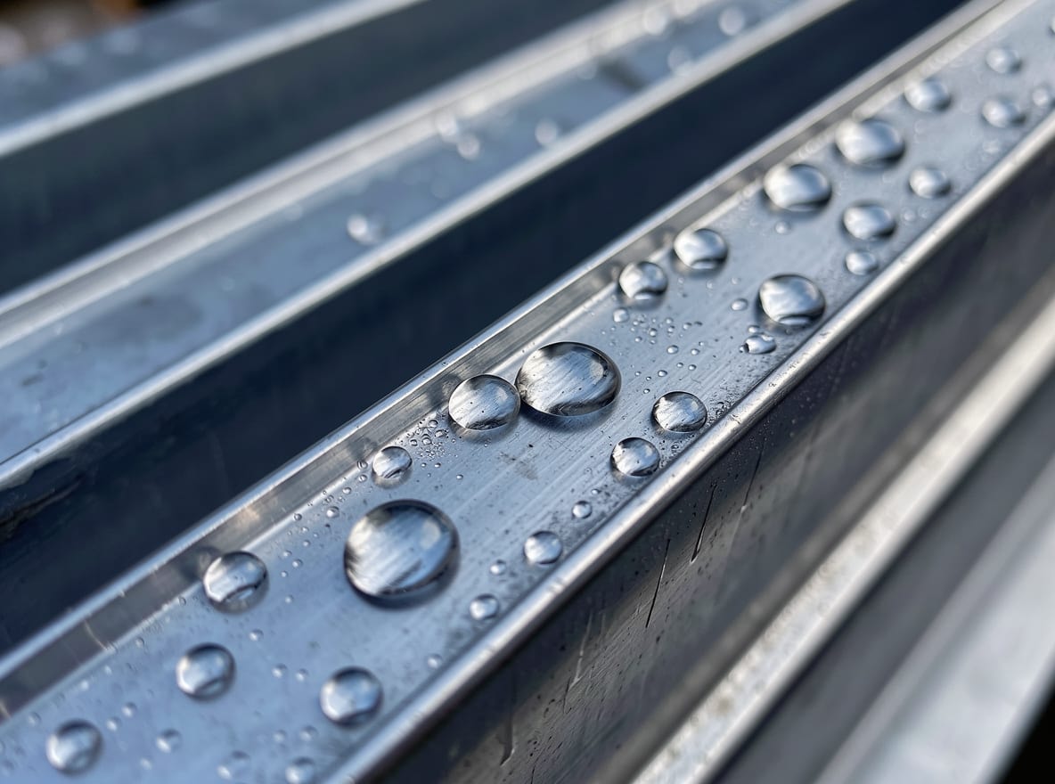
As moist air cools at the same pressure, it can draw closer to saturation even before any liquid forms. The dew point is the temperature at which that air reaches saturation. If a surface chills the air beside it below that point, vapor can condense on the surface [6] [7]. The beads that appear on the outside of a cold glass give a familiar view of this change. The vapor was in the surrounding air before the droplets appeared [6].
Engineers use psychrometrics, the study of the physical properties of gas and vapor mixtures, to connect the measurements [8]. A reading for relative humidity alone is missing the temperature it refers to. A temperature reading alone leaves the amount of vapor unknown. For a cooling design, the pair gives a way to estimate the dew point and compare it with the temperature the device can reach [5] [6].
Cooling air and collecting droplets
A cooling AWG moves air across a cold coil. Droplets form on the surface and drain into a collector. Air leaving the coil has lost some of its water vapor [1]. The diagram follows the air and the liquid along their separate paths. The coil must transfer heat from the incoming air to something colder. A heat exchanger lets heat pass between streams, for example through a solid wall that keeps them apart [9].
In a vapor-compression system, a circulating fluid called a refrigerant carries heat away from the air. The refrigerant takes up heat at the cold coil as it evaporates. The compressor raises the pressure and temperature of the vapor. At the condenser, the refrigerant gives off heat and returns to liquid. Its pressure then falls as it passes through an expansion valve on the way back to the cold coil [10]. The refrigerant flows around that circuit while the water droplets leave the coil for the tank.
A thermoelectric cooler moves heat across a solid module using electric current. Its cold side can cool air through metal fins, while the hot side gives up heat through a heat sink. The module is compact and has no moving parts of its own. Its limited efficiency and the need to carry away heat on the hot side matter when sizing a system [11] [1]. With either cooling method, the tank collects condensate. Designs intended to provide drinking water can include filtering and purification to deal with contaminants [1].
Desiccants and fog nets
A desiccant is a substance that takes up moisture. Water vapor can enter a liquid desiccant or collect at the surface of a solid material. A water harvester using this approach needs a step that frees the water and makes the material available for reuse. Heating the desiccant can release the water as vapor for condensation in a separate part of the system [1] [12]. The design has to account for the heat used in that release step, as well as how much vapor the material takes up.
Fog collection starts with liquid already present as fine suspended drops. As fog passes through a mesh, drops collect on the fibers, run down them and enter a trough. The mesh can operate passively. The material, gaps in the mesh and local supply of fog all matter to the amount gathered [2]. A site can have humid air without a steady supply of fog. The techniques describe different starting conditions for the water.
Water yield and energy use
A cooling unit's yield depends on the inlet temperature and humidity, the airflow over the coil and the available cooling capacity [1]. When the inlet air has little water vapor, there is less water in each volume of air to collect. A lower dew point also means the coil has to reach a lower temperature before condensation can begin [6]. Adding airflow changes how much vapor passes through the device and how much air it must cool [1] [10].
Heat leaving the hot side has to go somewhere. An air-cooled condenser passes it to the surrounding air. The volume of water that goes to the tank gives only a partial view of the cooling system's work. The system lowers the temperature of the moving air as well as condensing water vapor from it [1] [10]. A thermoelectric device also has to move heat against the temperature difference between its cold and hot faces, and a larger difference limits the efficiency it can reach [11].
A collection rate describes the volume obtained over time. Water per unit of energy answers a different design question. A concept that collects more water over the same interval could also use more energy. Putting both measurements together helps a team compare prototypes under like conditions. Reporting the inlet conditions alongside them makes clear which conditions the comparison covers [1] [3].
An engineering capstone on air and water
A capstone is a culminating project that brings together work from a course of study. It can take the form of a hands-on design project with a professional-style report [13]. The engineering design process includes setting objectives, comparing concepts, building and testing a design, and revisiting decisions as measurements come in [3]. A capstone on atmospheric water might set out to measure how a cooling design performs across a defined range of humidities.
A team could specify what a demonstration needs to show, where it could run and how much power is available. It could sketch the air, refrigerant and water paths to decide where to measure conditions. For a comparison of coil designs, a test plan could hold incoming air temperature and humidity steady, vary the coil, and record the volume and energy from each run. A separate test could vary the air conditions while holding the coil constant. Such choices illustrate how a test can help explain which change mattered [1] [3].
If a prototype collects little water, a team can compare the inlet dew point with the measured temperature at the coil. A surface warmer than that threshold gives a reason to review the cooling design. Seeing droplets stay on the surface would lead to a different question about getting liquid into the collector [6] [1]. The project report can explain what was tested, where the design fell short of its objective and what a further trial would need to measure [3]. A research position offers another way to encounter this kind of work, and the guide to presenting research covers how to turn a test and its results into a concise account.